THE RIG
The JETON rig has undergone several changes of measurement over the course of time (1970–1974). Since then the dimensions have remained unchanged. Since 1992 tapered masts have been permitted. The permitted thickness of the boom was increased in 1986. Since 1992 the boom may be tapered at the end. This chapter describes the rig in its current measurement.
Contents
- Mast
- Main Boom
- Spinnaker Pole
- Class Rules
- Dimensions of the Standing Rigging
- Trapezes
- Mast Controller
- Internal Halyards
- Jib Halyard / Rig Tension
- Main Halyard
- Spinnaker Halyard Systems
- Topping Lift / Kicker (Downhaul)
- Fittings for Trim Lines
- Sails
Mast
Mast Sections
Very old JETONs were equipped with very thin masts from Hahn. The corresponding sails had two full-length battens. What the measurement of the mast was, I do not know. This mast was very flexible, but a little too weak for the JETON.
Boats with numbers of about 200–800 were equipped with a somewhat stiffer mast with an almost round, teardrop-shaped section from Ermat. This “old Ermat mast” had the right flexibility. It was then replaced by the “new Ermat mast,” which was actually too stiff for the JETON.
When Ermat went bankrupt, Klepper had a very similar section made. This mast, known as the “Klepper mast,” had the same properties as the “new Ermat mast.” No “Klepper mast” is completely straight. The Gruben boats too were until now equipped with Klepper masts. Hans Spannheimer was the first to equip his boat with a Proctor mast. He chose the D-section, which in its untapered form also represents the optimum. In heavy weather one sometimes wishes for a somewhat more stable mast. The Proctor Epsilon or the M2 from Superspars have proved to be the optimum for the tapered mast. Both are said to have the same bend curve.
Tapered or Untapered
The taper of the mast produces an even mast bend curve up to the top. This is first of all an aerodynamic advantage. On the other hand, the more flexible top gives to leeward in gusts and opens the mainsail in the upper part. This takes the pressure out of the mainsail, the helmsman does not have to ease off so much, the crew does not have to move out and in so much. In the lower area the sail can remain fully set and continues to provide full drive. The tapered mast therefore makes the boat more comfortable, safer and faster.
Mast Length
All new Ermat and Klepper masts are about 3 cm shorter than they should be. The measurement band M0 therefore lies below deck height by this amount. Since this affected very many boats, the class rules were changed to take account of it (->Rule 12.3). Newly made masts should in any case be made to the correct length. The boom comes a little higher, which is good for the crew, and there is more wind up top.
Mast Measurement
The mast measurement is given in Fig. 4-1. It should be noted that the following dimensions are not fixed by the class rules:
- Attachment point of the forestay
- Height of the spreaders above M0
- Deflection/exit of the topping lift on the mast
- Height of the spinnaker pole eye above M0
Attention: On the Ermat and Klepper masts the fitting for attaching the shrouds, trapezes and forestay is fixed with one screw. The optimum position of this screw is 25 mm below the measurement band MVS (Fig. 4-2a). In the figure the forestay is not attached to the forestay adjuster as on the original mast, but simply
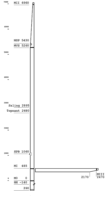
Fig. 4-1 Mast measurement
led through a small slot into the mast and fixed inside with a swage. This solution is particularly suitable for the old forestay adjusters when a roller jib is to be used, since with these the jib luff and forestay lie very close together. If one decides to lead the jib halyard inside the mast, the forestay adjuster can be dispensed with entirely. On masts with T-terminals the slots for the shrouds should be positioned so that the attachment point lies 50 mm below the measurement band MVS. The trapeze wires should attach directly at the band (Fig. 4-2b).
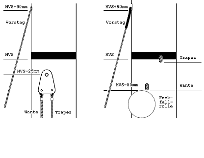
Fig. 4-2 Attachment of forestay, shrouds and trapeze wires, a. shroud adjusters, b. with terminals
The Measurement Band MVS
On older boats the measurement band MVS, i.e. the point on the mast where the forestay, shrouds, jib halyard sheave and trapeze wires are attached, is 100–200 mm lower than it may be under the now-valid class rules. Dimensions that must match the measurement band MVS (MSP, spreader height, spinnaker pole eye) are therefore also too low. With the introduction of the Klepper mast, the band MVS was set at 5260 mm above M0, i.e. 1700 mm below MII (at the masthead), and the class rules changed accordingly. This new dimension is considerably more favourable to windward.
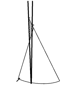
Fig. 4-3 Effect of the raised measurement band MVS
Why?
The main factor is that in the upper area the slot between mainsail and headsail is opened, as can be seen in Fig. 4-3. At the same time, if the jib clew is to stay at the same place, the mast rake is increased. This too, according to the experience of recent years, is favourable. If one tried to open the slot by mast rake alone, the clew would come too low and one would not have enough tension on the leech. It is also notable that with the old position of the band MVS the distance between the sheave on the mast and the forestay crown is so small that adequate tensioning of the luff wire is not possible, especially when the jib roller is used.
The difference is striking. This measure has proved thoroughly worthwhile. All—or almost all—regatta boats were converted.
Construction guide in Chapter 6.
Forestay
“Forestay (total)” in Tab. 4-1, 4-2 means the length that is required, with correctly set shroud length and with the rig just untensioned, to fasten the forestay with a shackle to the forestay crown. To prevent the forestay from dangling around when the jib is set, there are three options.
- The forestay is shortened by the length of a shroud adjuster plate and attached to the forestay crown with its help. With a shockcord strop the shroud adjuster plate is tensioned towards the stem fitting.
- One uses a forestay at full length and ties it towards the stem fitting with a shockcord strop.
- One shortens the forestay by about 30 cm and replaces the missing piece with a piece of Kevlar. Parallel to the Kevlar strop a shockcord strop (6 mm) is tensioned.
Spreaders
The height of the spreaders above M0 and the spreader length are not fixed by the class rules and vary on older boats, also because the height of the measurement band MVS varies. On the Klepper mast (the Gruben mast is the same) the spreaders lie 2680 mm above M0 and have a length of 450 mm. This has proved satisfactory.
Attention: Some spreaders supplied by Klepper are only 400 mm long and must absolutely be replaced.
The sweep of the spreaders, also called the spreader angle, influences the mast curve and thereby the mainsail profile in the middle area (cf. Chapter 7, section Mast Curve). The spreader angles are generally fixed with two screws or bolts. If this angle happens to suit the mainsail it is a happy coincidence. But there are also spreader adjusters with which the spreader angle can be set. A simple option without a spreader adjuster is described in Chapter 6.
Gooseneck
Ermat and Klepper masts have special gooseneck fittings that only fit the corresponding booms. The gooseneck fittings of the Proctor and Superspars masts are the same. One can therefore without further ado use a Proctor boom on a Superspars mast and vice versa.
If a Proctor or Superspars boom is to be used on a Klepper or Ermat mast, one needs a new matching gooseneck fitting. This is easy to fit. Conversely, if a Klepper or Ermat boom is to be used on a Proctor or Superspars mast, the end fitting of the boom must be adapted.
The gooseneck fittings should be firmly attached to the mast, e.g. with pop rivets. Below the measurement band MI the boom may not be used; above it the sail area is unnecessarily reduced. Mainsails today are normally cut so that the luff is relieved when the boom stands at the measurement band MI.
Main Boom
The Klepper JETONs are equipped with booms from Ermat or from Klepper. These booms are rather thin. While the Klepper boom just about provides the necessary stability, the Ermat boom is actually undersized. This applies above all if one wants to use a wire strop bridle and a correspondingly dimensioned kicking strap.
For new purchases, booms from Superspars or Proctor are to be recommended in any case. These are larger in cross-section and therefore more stable. They are only marginally more expensive.
Spinnaker Pole
Sections
The spinnaker poles supplied by Klepper or Gruben are of untapered tube with 30 mm Ø. Better are spinnaker poles that are thicker in the middle and tapered at the ends. A good spinnaker pole can be built oneself from a blank that is available commercially.
End Fittings
There are very many different end fittings for spinnaker poles. I like best the fittings known and sold under the name “Zalonghi fittings.”
Class Rules
Rigs with the un-raised band MVS or with a diamond are permitted under the class rules. The “old” JETON rig (before 1972, up to sail no. approx. 200) with two full-length battens in the mainsail is, by contrast, no longer permitted.
Dimensions of the Standing Rigging
The dimensions for the Klepper mast are given in Table 4-1. The values given apply to the normal Klepper mast, i.e. with the reduced length (see section “Mast Length”), otherwise laid out as given in Fig. 4-1 and Fig. 4-2. For the Ermat masts the dimensions apply if the band MVS has been raised (see section “The Band MVS”). A prerequisite is a spreader length of 450 mm. If one has a mast of full length available, the lengths of shrouds and forestay are to be changed accordingly.
Tab. 4-2 gives the dimensions for standing rigging with T-terminals (Proctor or Superspars). Fig. 4-2 b. shows the attachment points of shrouds, forestay and trapezes. The dimensions apply only with this layout of the mast and maximum length at the given spreader length of 450 mm. It should be pointed out that it is very difficult to give these dimensions generally. All possible configurations can hardly be taken into account. The figures are therefore given without guarantee. Particularly difficult is giving a length for the jib halyard, since there are various layouts of the jib halyard tensioner. The “free length of jib halyard” is the distance of the bolt in the shackle or in the fork terminal of the jib halyard from the measurement band MVS with the jib set and the rig tension not applied.
Tab. 4-1 Dimensions for mast with shrouds/trapeze/forestay adjuster
| Description | Dimension |
|---|---|
| Shrouds | 5100 mm |
| Forestay (total) | 5500 mm |
| Forestay (net) | 5210 mm |
| Forestay (total per Fig. 4-2a) | 5690 mm |
| Trapeze wire (single trapeze) | 4720 mm |
| Trapeze wire (continuous trapeze) | 4520 mm |
| Jib luff wire | 4960 mm |
| Free length of jib halyard | 490 mm |
| Spreader length | 450 mm |
Tab. 4-2 Dimensions for masts with T-terminals.
| Description | Dimension |
|---|---|
| Shrouds | 5170 mm |
| Forestay (total) | 5690 mm |
| Forestay (net) | 5400 mm |
| Trapeze wire (single trapeze) | 4720 mm |
| Trapeze wire (continuous trapeze) | 4570 mm |
| Jib luff wire | 4960 mm |
| Free length of jib halyard | 490 mm |
| Spreader length | 450 mm |
Trapezes
General
The Klepper and Gruben JETONs are usually fitted as standard with trapezes on both sides. Some Klepper JETONs have a continuous trapeze.
Length
The length of the trapeze should be measured so that the lowest position of the trapeze hook lies roughly at the rubbing strake. Rarely, especially in gusty wind, will one hang that low. But it should in principle be possible. Furthermore, the crew should be able to surface beside the boat when it has fully capsized, even if in the excitement they have not unhooked.
Two-sided Trapeze
With the two-sided trapeze one needs two tackles that allow the height of the trapeze hook to be adjusted, and one hook for each side. Before tacking or gybing the crew must unhook and hook on again on the new side.
Continuous Trapeze
With the continuous trapeze the crew hooks on to a trapeze hook or ring. This is attached to a block that can run over a shockcord from one trapeze to the other. At the trapeze the shockcord runs into a bracket on which the block then hangs (Fig. 4-4). The crew never needs to unhook. The brackets of the continuous trapezes used by Klepper were completely unsuitable. Most sailors, with the remark “I couldn’t get on with a continuous trapeze,” fitted two-sided trapezes. Unfortunately they never found out how practical a continuous trapeze is when it works. A few things must be observed for this:
- The bracket of the continuous trapeze should look roughly like in Fig. 4-4. It is important that the block does not run down off the bracket when the trapeze is not loaded. For this the bracket must be bent as shown in the figure. Also important is the position of the eye, which keeps the bracket horizontal.
- The shockcord should transition as smoothly as possible into the bracket, i.e. one should use as thick a shockcord strop as possible.
- The tackle for adjusting the trapeze should be attached above the bracket. Otherwise the bracket sometimes comes too high, and the block can get caught under the main boom during the tack. From the company FICO (…) there is a very nice continuous trapeze. Instead of the original shockcord, however, one should reeve a shockcord of 6 mm Ø.
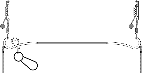
Fig. 4-4 Continuous trapeze
Mast Controller
All newer boats are equipped with a lateral mast guide, called a mast controller. This system has proved worthwhile and has displaced the diamond that was formerly usual.
The mast controller fitted as standard by Klepper and Gruben is made of stainless steel tube. It is screwed to the sloping transverse bulkhead. A disadvantage of this construction is that the mast controller gives somewhat to the lateral mast pressure. Very strong forces are exerted on the transverse bulkhead. On some boats the mast controller even pushed in the transverse bulkhead. The only remedy is a reinforcement of the transverse bulkhead or a support of the mast controller to the sides (construction guide in Chapter 6).
Hans Spannheimer was the first to build a very good mast controller with support onto the side deck. His construction is certainly to be regarded as the optimum solution for the JETON. Unfortunately it is too elaborate for series production. A simpler construction is given in Fig. 4-5. This mast controller is fitted as standard in the boats of the Berlin series and those from Robert Franz. For lateral guidance, strips are placed on both sides of the mast into the mast controller. The mast should be provided with a mast collar. The fore-and-aft bend of the mast should be limited to the front. This can be done either by wedges inserted into the mast controller between the mast and the crossbar in front of it, or by a mast puller mounted on the crossbars of the mast controller (Fig. 4-5).
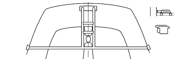
Fig. 4-5 Mast controller, wedges, mast puller
Internal Halyards
All masts from Ermat, Klepper and Gruben have external halyards. The branded masts from Superspars and Proctor are only available with internal halyards.
Internal halyards have the advantage that nothing can snag on the descending halyards. Everything is tidier and more orderly. A disadvantage is of course that the halyards are harder to haul in and that, if one does it clumsily, they can tangle inside the mast.
There is, however, one important argument for an internal jib halyard: the rig tension exerts a not inconsiderable compression load on the mast. The jib halyard runs down the front edge of the mast. I have often observed that the mast gives to the side under the compression load and slips off to one side. The jib halyard stays vertical, thus slipping to the other side. The mast then has a permanent lateral bend of about 50–100 mm in the middle. This of course sends all the trim to the devil. This happens the more easily the more mast bend is used. An internal jib halyard cannot slip off; the mast stays straight.
Jib Halyard / Rig Tension
The rig tension—the tension on the shrouds and the jib halyard/luff wire—is set on the JETON via the tension of the jib halyard. Adjustment via the shrouds, which would be better for the trim, is not permitted by the class rules, and is moreover considerably more elaborate technically.
The rig tension should be set to suit the wind strength. It may be trimmed while sailing. For this newer boats have a highfield lever (Bierkasten) mounted on the front of the mast. The highfield lever line can be operated from the cockpit. Older boats have only a perforated track with a tension hook, so that the rig tension cannot be adjusted while sailing. On several boats a tackle running freely at the centreboard case has proved worthwhile (Fig. 4-6; buttons are used to fasten the ends, Chapter 6).
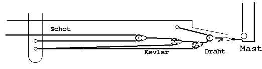
Fig. 4-6 Tackle for rig tension
None of the systems given allows the rig tension to be set from completely loose right up to the maximum value. The length of the jib halyard is therefore to be measured so that the rig already receives a certain pretension when hooked on. Without tension on the shrouds there should still be about 7 cm missing to bring the jib halyard onto the hook.
Main Halyard
Most JETON masts have a keyhole fitting at the masthead into which the main halyard can be hooked with the help of a ball swage. This is very elegant, since one has no stretch in the main halyard. Unfortunately the system is not entirely easy to operate, above all on the Ermat mast. The fitting on the Klepper mast works considerably better.
This system cannot of course be used with an internal main halyard. Here belaying on a rack at the bottom of the mast is suitable (Fig. 4-7).
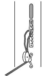
Fig. 4-7 Rack for main halyard
Spinnaker Halyard Systems
Overview
JETONs from Klepper or Gruben have no fittings as standard that allow a sensible spinnaker halyard lead. At the very least a sheave should be fitted near the mast foot to deflect the spinnaker halyard aft. Better is a spinnaker halyard running inside the mast, as fitted as standard on the Superspars and Proctor masts. The halyard then exits over a sheave in the mast foot or a lateral slot on the mast. The Ermat or Klepper masts can be converted relatively easily (Chapter 6).
The spinnaker halyard can then be belayed on one of the cleats on the traveller support. Two problems arise here: to hoist the spinnaker, 6 m of halyard must be pulled through by hand. The hoisted halyard then lies around in the aft cockpit and in the worst case disappears out through the self-bailers. The pulling-through can be simplified with a spinnaker halyard pump. For coiling up the halyard there are several, in part elaborate, systems. Both problems can be solved simultaneously by the spinnaker halyard tackle.
Spinnaker Halyard Tackle
The spinnaker halyard tackle is a device that, on the one hand, ensures that the spinnaker halyard is neatly coiled when the spinnaker is up and, on the other, makes it possible to hoist the spinnaker extremely quickly. The system has proved itself excellently on many boats. For it to work smoothly, a few small details must be taken into account.
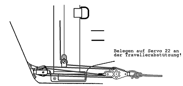
Fig. 4-8 The spinnaker halyard tackle
Function: The spinnaker halyard is deflected aft by a sheave on the mast and then runs into the tackle (Fig. 4-8). One block of the tackle is attached with a fender eye to the sloping transverse bulkhead; the other (with becket) is attached to a hauling line that is to be belayed on a Cleat (Curryklemme) on the traveller support. The end of the spinnaker halyard is knotted to the becket. It is an inverted tackle. To hoist the spinnaker one therefore needs five times the force, but only one fifth of the distance. If one pulls on the hauling line, one can let the spinnaker shoot up the mast with one movement. This works easily enough, because there is no pressure in the spinnaker that quickly.
Notes: The system works best, of course, with ball-bearing blocks. It also works with non-ball-bearing ones. It is important that a suitable spinnaker halyard is used. The spinnaker halyard should be of 4 mm braided, pre-stretched material. High-tensile materials are sometimes unsuitable here, since they do not twist easily. I have, however, had good experience with Dyneema, although this material too does not twist so well. The double blocks should have metal cheeks, since otherwise the cheeks are worn through by the fast passage of the halyard.
When the spinnaker is recovered, one should hold back a little so that the tackle does not get tangled. This can, however, also be achieved with a shockcord that is led forward again over a sheave at the transom and keeps the tackle taut.
Topping Lift / Kicker (Downhaul)
By Susanne Bräss The topping lift/downhaul system offered as standard by Klepper and Gruben is no longer used on any serious regatta dinghy today, since it is not only cumbersome but also nonsensical. It does not in any way meet the requirements of spinnaker sailing. The requirements for a well-functioning topping lift are as follows:
- Correctly holding the spinnaker pole at a set height. It must not allow the pole to sag, since this would cause the leeches of the spinnaker to close.
- In a gust the spinnaker should have the possibility of releasing surplus force; this is achieved by allowing the pole to rise elastically up to a stop. A topping lift system usual today on regatta boats is shown in Fig. 4-9.
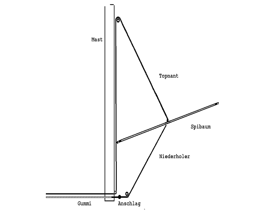
Fig. 4-9 Topping lift/downhaul system
The topping lift runs down the mast over a sheave at roughly spreader height, is deflected at the mast foot and is belayed somewhere. It serves to adjust the system. The downhaul is deflected aft near the mast foot and runs into a shockcord strop that is fixed somewhere, e.g. on the traveller support or on the centreboard case, e.g. with the help of a button (Chapter 6). Where the downhaul and shockcord strop are knotted together, a stop (ball) is fitted, set so that the pole can rise about 10 cm higher than the usual highest position used.
The topping lift and downhaul should be of Kevlar, Dyneema or (braided) wire, so that there is not too much stretch in the system.
It is advisable to run the topping lift, like the spinnaker halyard, inside the mast. The entry sheaves for the topping lift can be laid out just like for the spinnaker halyard (see section “Internal Halyards” and Chapter 6).
There are differences in the belaying of the topping lift. Three systems are used:
- On the thwart beam or the traveller support amidships. This is technically the simplest method. The topping lift is simply deflected aft and belayed on a cleat on the thwart beam.
- On the thwart beam or the traveller outboard. Then a doubling block is of course necessary (Chapter 5). Here a block must be fitted at the end of the topping lift, through which a line is pulled that is deflected to both sides at the thwart beam or traveller and belayed there.
- Forward, in the crew’s area. Here the topping lift is led forward from the mast, and a block (doubler) fitted at its end. The line is led outboard over two blocks on each side (see Fig. 5-6). Which version is most suitable depends very much on the skill of the crew. The crew can see the spinnaker much better than the helmsman and should therefore normally also set the topping lift. If the crew is still inexperienced, however, it is better if the helmsman sets the topping lift.
Fittings for Trim Lines
The trim lines that come from the mast must be deflected at the mast foot. Mounting deflection blocks on the double bottom with the help of fender eyes, as can be seen in Fig. 5-11, is not to be recommended on Klepper or Gruben boats, since no aluminium plates are laminated in. Deflection blocks must therefore be mounted on the mast. This is best done with pop rivets or self-tapping screws. An example of the trim line lead on the Klepper/Ermat mast is shown in Fig. 5-11. Lying blocks as in Fig. 4-8 can likewise be used.
Sails
General
To discuss the subject of sails here at length would exceed the scope of this book. Only a few technical matters shall be mentioned.
Jib Measurement
Old JETON jibs were somewhat shorter in the luff than the current ones and therefore fitted well with the low-lying measurement band MVS. Whoever has a mast with the very low-lying band MVS (1900 mm below MII) usually has problems with a new jib. So raise MVS (Chapter 6)!
Mainsail Measurement
If one uses the measurement rule fully for the mainsail, the leech has a bulge to the rear in its lower half. That is why most sailmakers cut the mainsail so that the dimension 3/4W is shortened by about 100 mm.
Tack Lashing
The mainsail tack of the old Klepper sail fits quite well with the tack pin on the Klepper boom. Unfortunately there is otherwise hardly a tack that fits any tack pin. Furthermore one wants to be able to use the tack tighter or looser depending on the weather. So: forget the tack pin and simply tie the tack around the mast with a piece of Kevlar! (Fig. 5-11).
Spinnaker
The most important spinnaker cuts are:
- Crosscut The spinnaker consists only of horizontal panels. The cut is simple. Nevertheless crosscut spinnakers are very different depending on the concept. The old Klepper spinnakers were crosscuts. But they were cut very full and pulled almost not at all on close courses. Modern crosscut spinnakers are cut flat.
- Radial head This cut has radial panels in the head area, i.e. the panels begin at the head and run downwards and end at about half height. They are narrow at the head and become wider towards the bottom. The lower panels are horizontal. These spinnakers can be cut wide in the upper area, mostly let themselves be pulled flat well, so that they also work well on closer reaching courses.
- Triradial This cut is optimal in terms of trim, since all panels run in the direction of load. Attempts were made several times to cut dinghy spinnakers this way too. It turned out, however (e.g. on the Korsar), that the spinnaker becomes too heavy because of the many seams. For the JETON there are both crosscuts and radial heads. Formerly almost only crosscuts were used. In the 1980s there was a trend towards the radial head. Recently one sees again—in other classes too—more crosscuts, which are, however, cut very flat.