FITTINGS
Contents
- Jib Fairlead
- General
- Mainsheet Lead
- Spinnaker Sheet
- Sheets
- Centreboard
- Rudder/Steering Gear
- Trim Lines
Jib Fairlead
General
The jib trim is essentially determined by the jib sheet fairlead. The position of the fairlead determines the jib angle and the profile depth of the jib. In addition, the height of the fairlead determines how much mast rake (aft inclination of the mast) can be used. All three parameters strongly determine the windward behaviour. The optimum layout of the jib fairlead is therefore very important for the performance of the JETON on the beat.
The standard fairlead track of the Klepper and Gruben boats clearly lies in the wrong place, so that with this arrangement a JETON does not point to a satisfactory height. The standard windward belaying is likewise unacceptable.
In the 1984/85 yearbook I gave an overview of the fairlead designs used at that time. This was in the course of the discussion about making the fairleads free (unrestricted). Some of the designs are outdated today but are still partly in use. Here only two concepts are described that have proved themselves. As a supplement, the fairlead with leeward belaying on the original track is also mentioned. All designs used today have leeward belaying. The cleat should be mounted inboard on the side tank, so that the deck is free to sit on. No boat on the regatta scene uses the windward belaying and jib sheet lead still offered by Gruben today.
Belaying
With both designs the jib sheet is belayed on a cleat that is mounted with a deflection block on a bracket on the side tank. The bracket is available as a retrofit fitting through the ASJETON. Commercially available parts are more expensive and less well suited to the JETON.
Fairlead on Track
The jib fairlead is located on a track attached inboard on the side tank. The fairlead lies about 6 cm below the deck edge and can be adjusted longitudinally with the help of the track. Since the cockpit becomes wider towards the rear in this area, the track runs somewhat at an angle. The track is usually a simple perforated track. It can be screwed directly to the side tank (Fig. 5-1b). Then a slide with an angle bracket, on which the block is then mounted upright, is advantageous. But an angle section can also be used that allows horizontal mounting of the track (Fig. 5-1a). The block can then be mounted upright directly on the slide.
Variants:
Some do-it-yourselfers have also mounted the cleat on the angle bracket at the same time.
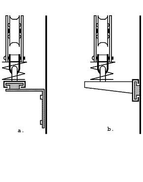
Fig. 5-1 Tracks for jib fairlead,
a. On angle track,
b. Directly on the side tank
If one uses the angle bracket on the slide, lateral adjustability of the fairlead can also easily be achieved. A particularly elegant solution is a remotely adjustable fairlead. The perforated track is then replaced by a small traveller track and the fairlead mounted on the traveller car. Fig. 5-2 shows the arrangement of the fittings and suggestions for the line lead of the remote fairlead adjustment. The adjustment line can also be belayed on the centreboard case collar (Fig. 5-12). Commercially there are also, though at proud prices, complete systems with perforated track or traveller, also with additional lateral adjustability of the fairlead. Whoever wants to do it themselves can use the old fairlead track mounted on the deck and should obtain suitable aluminium angles from a metal supplier.
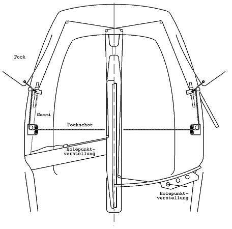
Fig. 5-2 Jib fairlead on track, lead of the remote fairlead adjustment
Free-flying Fairlead with Windward Adjustment
After Walter Stupp
The fairlead is attached to a block that can run freely on the adjustment line. Although this design is simple and inexpensive, it has a number of advantages (see below). In a boat with a traveller the adjustment line is to be led as follows (Fig. 5-3): the adjustment line is fixed directly behind the mast on the keelson (A). The screws with which the toe straps are fastened can be used. The other end runs over a block that forms the second reference point of the fairlead (B). The adjustment line is deflected once more at the traveller (C) and belayed on the windward side on the trim bench.
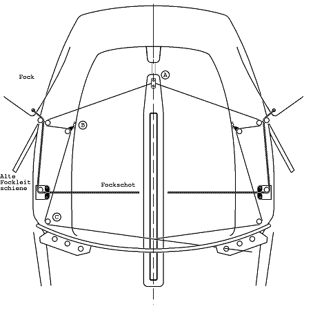
Fig. 5-3 Free-flying jib fairlead
This lead is not so well suited to a boat with a thwart beam and centreboard case collar, since here the adjustment line would run over the centreboard case. Here the fixed end of the adjustment line should lie outboard (2), the block be fitted on the keelson (1). The adjustment line can then be led under the centreboard case collar and belayed as in Fig. 5-2. Alternatively the adjustment line can be led up through a slot and belayed on the centreboard case collar as in Fig. 5-12.
Fairlead on the Standard Track
The two designs described above require, when retrofitted to an old boat, a considerable amount of rebuilding work. Inspection hatches must be fitted, stiffeners glued in and parts screwed to the hull. If one mounts a fairlead with leeward belaying on the standard track, everything is much simpler. Construction guide in Chapter 6.
The fairlead systems compared:
Fairlead on track:
- The deck is free to sit on.
- The system works even without remote adjustment.
- Everything is screwed down and does not fly around in the cockpit.
- Remote adjustment from windward is possible but not inexpensive.
Free-flying fairlead:
- The deck is free to sit on.
- The space in the cockpit is not obstructed.
- Remote adjustment from windward is inexpensive.
- Adjustability within wide limits (corresponds to a jib track of about one metre length).
- On a reach the fairlead automatically lies well forward.
- When retrofitting, a reinforcement of the tank is only needed for the bracket with the cleat.
Fairlead on the original track:
- No installations in the hull.
- The jib fairlead on deck still gets in the way as before.
Mainsheet Lead
Belaying
The standard belaying of the mainsheet is a cleat on the side deck. If one prefers this kind of belaying, one should at least use a smooth-running sheet cleat (SERVO 22 from Spring), better still a ball-bearing cleat, HK150 (Harken).
On almost all regatta boats a centre belaying has become established, either a block combined with a Cleat, or the Mubir block.
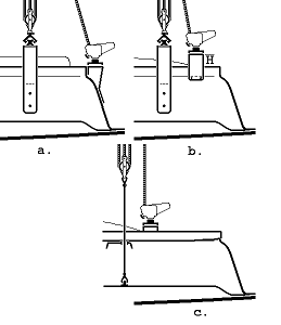
Fig. 5-4 Mainsheet belaying,
a., b. with mainsheet table
c. Mounting on centreboard case collar
Unfortunately there is no place on the JETON that is suitable for mounting such a device. A special part is therefore necessary. Figs. 5-4 a and 5-4 b show the mainsheet table, as it was offered some time ago as a retrofit fitting and fitted on the boats of the Berlin series. The fitting in Fig. 5-4b is the better solution, because the mainsheet belaying lies further forward. One has more room during the tack. (Construction guide in Chapter 6). The height (H) given in Fig. 5-4 b. can be varied depending on the outline of the centreboard (cf. section Centreboard). A good mounting possibility is offered by a centreboard case collar. If a centreboard with an elliptical outline (cf. Fig. 5-8) is used, one can screw directly onto the top. Fig. 5-4c shows the arrangement of the Robert Franz JETONs with thwart beam and wire strop bridle. The mainsheet belaying deliberately lies well forward.
Traveller or Wire Strop Bridle
There are a number of arguments in favour of the traveller or the wire strop bridle (see also the article by Erich Beer in the appendix):
Traveller:
-
The traveller is an additional trim device that allows flattening of the mainsail.
-
The traveller can provide additional stability as a transverse member.
Wire strop bridle:
- The “sheeting in” function is separated from the “hauling down” function. Operation is thereby made simpler. One string is eliminated. The effect of the traveller is then achieved by the kicking strap. The mainsail can then be trimmed by the mainsheet alone. The prerequisite is that the kicking strap has a sufficient purchase and the mast bend in the deck area is sufficiently controlled. Furthermore the main boom must be stable enough. (The Ermat boom is probably somewhat weak.)
- Because of the more horizontal sheet pull one needs less force.
- The traveller lies very far aft on the JETON. This is exacerbated by the curvature of the traveller. If the helmsman sits behind the traveller, as is most comfortable, this is generally too far aft, except in a lot of wind.
- The traveller lies at deck height and prevents the helmsman from sliding or climbing forward.
- Because of the round shape and the not very stable support of the traveller, a possible stabilization of the hull, especially of the centreboard case, is not provided.
Boats without a Traveller
On some boats the traveller was removed without an additional lateral support being fitted. The stability of the hull and of the centreboard case is not impaired thereby. All these boats, however, have wooden centreboard case collars.
On Hans Spannheimer’s boats the traveller was replaced by a straight aluminium tube. The centreboard case was stabilized laterally at its aft end by a stable support fastened to this tube. The Robert Franz JETONs have no traveller. A thwart beam serves to laterally stabilize the centreboard case and to screw on the cleats for the trim lines.
Transom Mainsheet Lead
Instead of fitting the wire strop bridle in the area of the thwart beam, one can also let the mainsheet attach at the boom end. For this a wire strop bridle is fitted at the stern (measured about 30 cm from the transom).
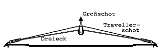
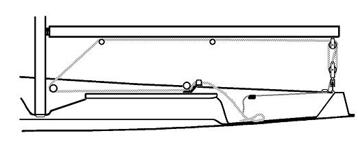
Fig. 5-5 Transom mainsheet lead
The mainsheet then runs forward along the boom, down parallel to the kicking strap, and aft again over the centreboard case. Belaying is done on a rotatably arranged Cleat after deflection over an upright block (Fig. 5-5). Alternatively the sheet can also be deflected downwards in the area of the thwart beam and belayed there, e.g. on a Mubir block (Fig. 5-4). The legs of the wire strop bridle are fastened with fender eyes screwed through the glue joint of the rubbing strake. The wire strop bridle in Fig. 5-5 additionally has a traveller function. The mainsheet can run back and forth on a block, or be pulled. Two blocks with becket, mounted between the bridle leg and the fender eye, serve to deflect the traveller lines. The advantage of the transom mainsheet lead is that freedom of movement in the cockpit is considerably improved. The mainsheet hinders neither helmsman nor crew. The mobility of the tiller extension is, however, somewhat restricted by the transom mainsheet lead. During the tack it must be swung around the front. This requires some practice but works entirely without problems.
The Tackle
The tackle of the mainsheet should have four or five parts. With six parts one has too much sheet to move. A four-part tackle indeed requires 20% more force but is more direct in handling the sail and runs more easily. Whoever is in good shape strength-wise manages with four parts. It is to be noted that the force needed to haul the sheet also depends on where on the main boom the mainsheet attaches, i.e. how long the lever arm is. If one sets the mainsheet somewhat forward, as on the Robert Franz JETON, one therefore needs more force.
A wire strop bridle reduces the necessary force somewhat, since the sheet pull attaches more horizontally. For a transom mainsheet lead two parts are sufficient.
Spinnaker Sheet
Lead
The spinnaker sheet should be run continuously, i.e. the starboard and port sheets are knotted together at the ends or are of one piece. The spinnaker sheet should run over three blocks on each side:
- Fairlead block
This block lies at the stern, or, depending on taste and spinnaker cut, somewhat further forward, outboard.
- Deflection block at the stern, inboard.
- Deflection block at the thwart beam or traveller.
All these blocks should absolutely be ball-bearing. Fig. 5-6 shows the arrangement of the spinnaker sheet blocks. The deflection block at the stern, inboard, is mounted in the wrong place on the Klepper and Gruben JETONs. The sheet rubs on the deck. The correct position is where the flat upper edge of the transom passes into the side tank, as visible in Fig. 5-6.
On older JETONs the outboard fairlead block is absent, so that the deflection block at the stern is effectively the fairlead. The outboard fairlead block is, however, easy to retrofit. It can simply be screwed through the glue joint. Instead of the deflection block at the traveller, an eye is fitted on the Klepper and Gruben JETONs. This is completely unsuitable, since it offers the sheet far too much friction. A block can be shackled to the eye. Alternatively fender eyes with blocks can be screwed on.
Barber Hauler
Very few JETONs are equipped with barber haulers for the spinnaker sheet (Fig. 5-6). The spinnaker sheet is pulled through a light block or a nylon ring attached to the barber hauler. With the windward barber hauler the after guy is pulled right up to the shroud chainplate. With the leeward barber hauler the pulling angle of the lee sheet can be trimmed.
Belaying
When spinnaker sailing, actually only the after guy (windward sheet) needs to be belayed. The after guy runs under the hook at the shroud chainplate and should be belayed on a Cleat directly behind it. If a barber hauler is used, the hook is not needed. The barber hauler then serves to lead the after guy. On Klepper and Gruben JETONs this cleat is not present as standard. It must be fitted afterwards. The spinnaker sheet cleat mounted on the deck (next to the traveller cleat) is not suitable for belaying the after guy. The sheet should always be handled from the hand. In calm wind one can also belay the sheet occasionally. The windward cleat present on Klepper and Gruben JETONs next to the traveller cleat is suitable for this. But one can also build a bracket with a leeward belaying similar to the jib sheet leeward belaying (for this there is unfortunately no construction guide).
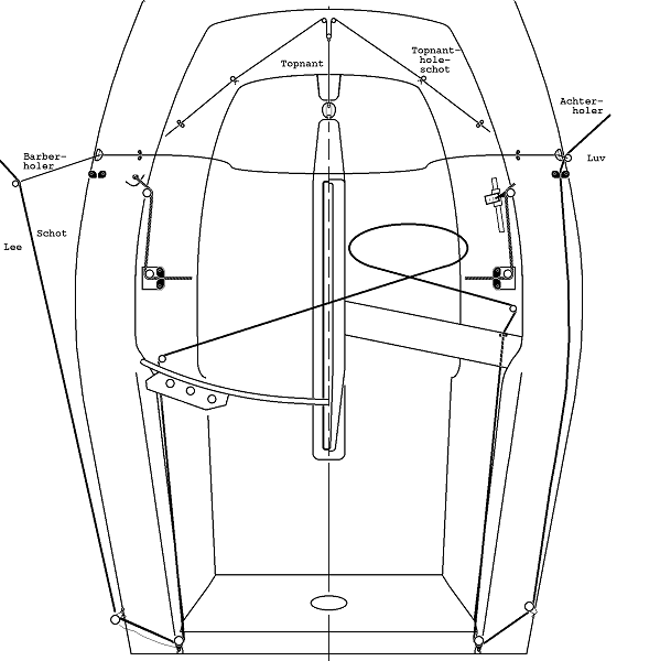
Fig. 5-6 Spinnaker sheet lead with barber hauler and topping lift line
Sheets
Material
Mainsheet and jib sheet should be of 8 mm braided, pre-stretched rope. 10 mm sheet material, as supplied by Klepper and Gruben, is more expensive, heavier, runs unnecessarily hard, and is only to be recommended if one has problems because of delicate hands. The mainsheet is mostly rove as a four- or five-part tackle. The spinnaker sheet should be run continuously. Best suited are tapered spinnaker sheets (6–4 mm) with a Kevlar core or of Dyneema.
Lengths
| Name | Length | Note |
|---|---|---|
| Jib sheet: | 8.50 m | |
| Mainsheet: | 10.00 m | five-part tackle |
| Mainsheet: | 8.00 m | four-part tackle |
| Spinnaker sheet: | 18.00–22.00 m | to taste |
Sheet Blocks
All sheet blocks, especially those of the spinnaker sheet, should be ball-bearing.
Centreboard
Overview
The centreboard is a part of the boat that most JETON sailors—apart from capsizes—have never fully seen. Most know only the trailing edge. Correspondingly little attention is paid to the centreboard. Yet it is of eminent importance for the performance of the boat. The centreboard has the task of preventing the leeway of the boat, above all on a windward course. It acts like a hydrofoil in the water. The lift force of the foil opposes the side force generated by the sail.
Although in principle any board that corresponds to the dimensions, and is bevelled somewhat at the edges, can serve as a centreboard, the profiles, the optimum outline, the stability and the surface decisively influence the hydrodynamic effectiveness of the centreboard and thereby the windward performance of the boat. One should also care for a centreboard, i.e. inspect it now and then and repair damaged areas. On wooden centreboards the varnish should not show too much damage.
Stability/Durability
From an article by Hans Spannheimer:
There are probably few JETON sailors who have not yet had trouble with the original centreboard. The reason for the trouble is always the same. The centreboards break under stronger load parallel to the grain direction of the wood. With the old 20 mm centreboards a strong gusty wind was often already enough; with the newer 28 mm centreboards it cracks at the latest when one climbs onto the centreboard after a capsize. Since the solid mahogany used by Klepper and Gruben is as a rule of the best quality, one could expect a long life at least for the 28 mm centreboards. If this is not so, it is due to the very unfavourable shape of the centreboard.
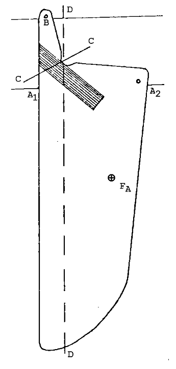
Fig. 5-7 JETON centreboard with carbon-fibre reinforcement
When sailing to windward, the wind generates not only a driving force but also a lateral force. This lateral force is compensated by an equally large opposing force F acting on the centreboard (Fig. 5-7). F is termed lift in flow theory. F does not attach, as one might at first suppose, at the area centroid of the centreboard, but much further forward. On the JETON centreboard this attachment point is about 11–12 cm from the leading edge. At the points A1 and A2 the centreboard rests on the lower edge of the centreboard case. The resulting torque is compensated by a second one, caused by a force acting at point B (support at the upper edge of the centreboard case). Through these attaching forces the centreboard bends. The greatest bending occurs at section C-C. One can now resolve this bending into a component parallel to the grain direction of the wood and one perpendicular to it. Since the bending strength perpendicular to the grain in most woods is less than 5% of the value parallel to the grain, the centreboard breaks at section D-D. This also applies to strip-laminated centreboards.
Conclusion: Centreboards should always be reinforced with glass fibre/carbon fibre and epoxy resin. This applies above all to profiled centreboards, which after all taper thin at the trailing edge. One possibility is to reinforce the centreboard with a stiff carbon-fibre material and epoxy resin. In Chapter 6 Hans Spannheimer’s method for reinforcing the centreboard is described. This is suitable above all for reinforcing already existing centreboards. If a new centreboard is to be purchased, one should choose a centreboard that is already reinforced over its entire surface.
Material
The original centreboards from Klepper or Gruben are of solid mahogany or plywood. Optimal are strip-laminated centreboards with reinforcement of glass cloth, carbon fibre and epoxy resin.
Thickness
The centreboard cases of the older boats have a clear width of 24 mm. The matching centreboards are 20 mm thick. The centreboard cases of the current moulds have a clear width of 30 mm. Here centreboards with the maximum thickness of 28 mm can be used. This maximum thickness should also in any case be exploited.
Outline
The outline of the template of the JETON centreboard is trapezoidal with rounded corners. The length of the centreboard head of the previous centreboards requires that the centreboard is raked aft even in its lowest position. Furthermore the maximum depth of the centreboard would be exceeded. A trapezoidal outline is not the worst, but an elliptical one would be better (appendix). However, it has turned out that raking the centreboard aft, which after all looks so streamlined, worsens the performance of the centreboard. The class rules fix only the maximum outline of the centreboard. About the rake angle they say nothing, though the maximum depth of the centreboard is limited.
One can therefore “make the centreboard outline elliptical.” In doing so one should ensure that the leading edge becomes straight (Fig. 5-8). One can reduce the rake angle if the maximum depth is not exceeded. If one lengthens the centreboard head somewhat and fits additional guides into the centreboard case, one can tilt the centreboard more towards the vertical.
There are already elliptical centreboards. These are somewhat smaller in area than the original centreboards. In my experience the smaller area is by far made up for by the optimum outline. There are no problems with leeway to windward at any wind strength. Only when the boat is (almost) stationary, with no flow at the centreboard, does one have the feeling the area could be larger. Up to now the effect of the reduced rake angle of the centreboard has not been tried out. The next new boats will show what it brings.
Profile
The discussion about profiles is similar to the discussion about sail cuts. There is much that is a matter of feeling. The effect of the details of the profiles, i.e. of the exact course of the profile contour, is very hard to test. One is dependent on the manufacturers using good profile data, optimized somehow, by model calculations or in the towing tank. One thing is, however, clear: any streamlined profile is better than a board with bevelled edges. (Do-it-yourself suggestion by Jupp Zavelberg in Chapter 6.)
In the appendix, fundamentals about profiles are discussed. For the JETON centreboard it follows from this: both lift profiles and laminar profiles are suitable. Even with a laminar profile a flow separation rarely occurs at the centreboard, since the lift pressures are not so great. Compressed profiles are seen less often today.
Weight
Interestingly, the class rules fix only a maximum weight of the centreboard (8 kg), although the weight of the centreboard is supposed to play no role in the stability of a dinghy. One should therefore make the centreboard as light as possible. A good strip-laminated centreboard reinforced with glass/epoxy weighs at most 6 kg. If one wants to go even lighter, it becomes more expensive.
Guiding of the Centreboard
The guiding of the centreboard should be arranged so that the centreboard is fixed laterally in every position in the centreboard case. If it has play, it does not stand vertically in the water even at a level floating attitude, owing to the lift pressure, which worsens its effectiveness. To guide the centreboard, it must be fixed at three points, provided the centreboard is stiff enough in itself. The concept of the centreboard guidance on the JETON is in principle correct, if one disregards that a differently shaped centreboard head and a centreboard case lengthened forward would be more favourable for stability. The three fixed points are:
- the centreboard pivot point (A),
- the bearing point on the vertical guide strip in the centreboard case at the bottom (B),
- the bearing point on the guide strip at the top (C). Unfortunately this is only so “in principle,” for:
- in the raked state the centreboard head moves forward and no longer rests on the guide strip.
- The clear width between the guide strips is at the top already greater than the centreboard thickness (about 33 mm on the current moulds) and furthermore becomes still greater towards the bottom. That is why the JETON centreboard is known to rattle in the centreboard case. For proper centreboard guidance one needs:
- a horizontal guide strip at the upper edge of the centreboard case,
- a vertical guide strip, as already present. The spacing of all guides should correspond exactly to the centreboard thickness.
In the lowered state the centreboard rests with its entire head on the vertical guide strip. In the raked state the centreboard head rests on the horizontal guide strip. On the vertical guide strip lies the thickest part of the profile. The centreboard is therefore fixed in every position. Glued-in pieces of sail batten are suitable as guide strips. The vertical pieces must, however, be wedge-shaped (construction guide in Chapter 6).
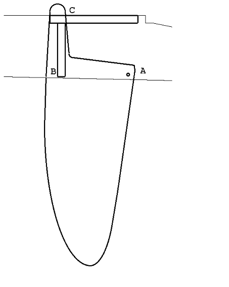
Fig. 5-8 Centreboard guidance, centreboard with elliptical outline
Centreboard Control Line
There are various ways of leading the centreboard control line:
- The centreboard control line consists of a separate uphaul and downhaul. Both are belayed each on a cleat. When the uphaul is hauled, the downhaul must be eased. To mitigate this circumstance, a shockcord strop can be inserted into the downhaul.
- The continuous centreboard control line. Uphaul and downhaul are “continuous,” i.e. of one end that is led back over blocks. The advantage of this design is that no cleat is necessary. The system has enough friction that the centreboard is fixed. Crew and helmsman can both operate the centreboard. It is important that the necessary change of length of the continuous centreboard control line is compensated by a shockcord strop. Fig. 5-9a shows a design that can be fitted without great effort in the Klepper or Gruben JETON. The centreboard control line runs over a block that is partly already present (A), a block that is fastened to the inner transom via a shockcord strop (C) and two lying blocks screwed to the centreboard head (B). Block C can also, e.g., be knotted to the traveller support. Then the centreboard control line does not run through the aft cockpit. This principle can be realized particularly elegantly with a centreboard case collar (Fig. 5-9b). Block C is replaced by two lying blocks mounted on the centreboard case collar (D). The control line disappears through a hole in the centreboard case collar (E). The shockcord strop lies under the collar. Block A must be attached to a short wire or Kevlar strop. Construction guide in Chapter 6.
Centreboard Slot Gaskets
For centreboard slot gaskets one uses strips of Mylar film. The template material of sailmakers (e.g. from Clown) is suitable. But there is also, in the boating supply trade, Mylar with a cloth coating from the roll. This material is intended for gluing on without aluminium strips and screws, which on the JETON, however, does not work so well.
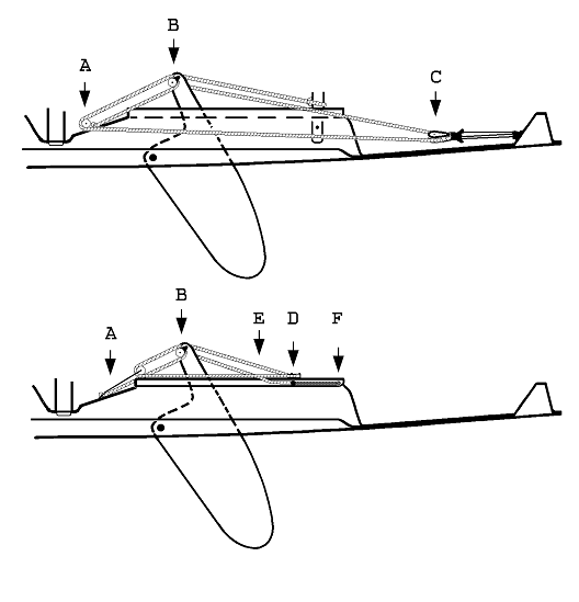
Fig. 5-9 Continuous centreboard control line lead,
a. In the Klepper/Gruben JETON,
b. With centreboard case collar
Rudder/Steering Gear
Outline
The maximum outline of the JETON rudder is fixed by the class rules. But it may be smaller as desired. The maximum outline is possibly good in light wind, but as an all-round rudder it is too broad at the bottom. As described in the appendix, an elliptical outline that tapers somewhat near the hull is optimal. Such an outline can be inscribed very well into the original template and is thus in conformity with the class rules. Fig. 5-10. Such rudders are offered by two manufacturers and have proved themselves. The smaller area is offset by the optimum outline. On a reach one sometimes wishes for somewhat more rudder effect, but that is rather a general problem.
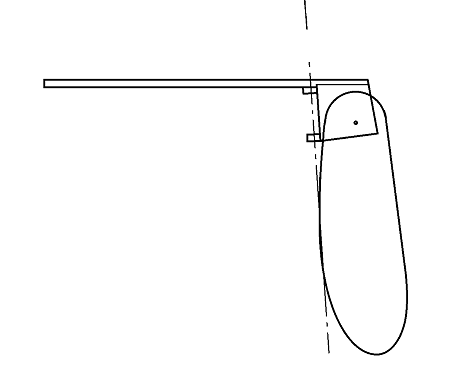
Fig. 5-10 Rudder outline/balance
Balance
The class rules do not fix the rake angle of the rudder in any way. The maximum depth of TR=600 mm must, however, be observed. How should one choose the rake angle of the rudder?
- The rudder should stand as vertical as possible.
- The rudder should be slightly balanced.
With a fully balanced rudder the pressure point lies on the pivot axis, so that one feels no rudder pressure. This is not desired. On the other hand the rudder should be very easy to operate. The pressure point should therefore not lie too far behind the pivot axis. If one uses the original outline and the original Klepper rudder head, the rake angle of the rudder is predetermined: the leading edge of the rudder has roughly the direction of the transom, the trailing edge of the rudder is raked aft. In this position the pressure point of the rudder lies clearly behind the pivot axis. The rudder is therefore anything but a balanced rudder. A good rule of thumb is: the leading edge of the rudder blade should intersect the pivot axis or cross it by up to 30 mm (Fig. 5-10).
Profile
As with the centreboard, lift profiles and laminar profiles are used here too. Lift profiles have proved themselves. Laminar profiles are less suitable, since they require a very sensitive handling of the rudder, but they have a lower flow resistance.
Thickness
The thickness of 30 mm is optimal and should always be exploited.
Weight
The entire steering gear should weigh no more than the minimum weight of 4 kg fixed by the class rules. Original rudders of mahogany are generally too heavy. Good strip-laminated rudders reinforced with glass/epoxy come to about the right weight.
Material
The original rudders, like the centreboards, are either of solid mahogany or plywood. Optimal rudders are of strip-laminated material with reinforcement of glass cloth or carbon fibre with epoxy resin.
Steering Gear
To obtain good steering gear for the JETON is not easy. The original rudder head from Klepper is of die-cast aluminium. It is indeed very stable but unnecessarily heavy.
Good rudder heads from Cee-Vee are available at Vesting & Siegmund.
At Klepper the JETON tillers ran out at some point. Therefore the JETON was for a time equipped with trainer tillers, which are much too short. The correct length of the tiller is at least 1 m, measured from the rudder fitting. A tiller that is too short tempts the helmsman to sit too far aft. One can make the tiller even longer if one is slim or uses a mainsheet belaying that lies further forward. Unfortunately the square section of the tiller tube is not available in the metal trade. If one wants to equip the original rudder head with a longer tiller, only the radical do-it-yourself suggestion in Chapter 6 helps.
The original tiller extension is a simple batten. Better is a commercially available extension of aluminium tube with a golf-club grip. The tiller extension should be 1.10 m long. The extension should be attached at the end of the tiller and not, as with the original steering gear, 12 cm further aft. This unnecessarily shortens the effective length of the tiller.
Rudder Fittings
The original rudder fittings from Klepper could be somewhat more stable. Those from Gruben are too large. Commercially available rudder fittings are mostly too short for the JETON because of the projecting trailing edge.
Trim Lines
The original equipment of the Klepper and Gruben boats is rather spartan. The trim lines are all there, but cannot be operated while under way and certainly not from the hiking position. If one is content with that, the trim lines are not an issue. On a regatta boat it is very helpful, if not indispensable, that the trim devices can be operated while under way, i.e. they must be easily reachable and smooth-running. The lead of the trim lines depends very much on the personal preference of the crew. Fig. 5-11 shows the fitting-out of the boats of the Berlin series.

Fig. 5-11 Trim lines on the Berlin JETON
Belaying
Most trim lines come from the mast and run into the cockpit, where they are belayed. Trim lines should be operable from the hiking position if possible. That is, the cleats should lie outboard, or at least the pulling direction should be athwartships, so that they can be hauled from the side.
- Cleats on the traveller support This option is only suitable for rarely used lines, since the pulling direction is aft. The helmsman must move into the aft cockpit.
- Cleats on the side of the centreboard case with pulling direction aft.
For this the same applies as for belaying on the traveller support. It should be pointed out that on the centreboard case there are no reinforcements for screwing on cleats, except at the traveller support. On a new boat one can of course have them glued in, if one thinks of it in time.
- Cleats on the centreboard case collar.
A centreboard case collar, whether self-built of wood (Chapter 6), a retrofit one from Robert Franz or a standard one, is very well suited for mounting the trim line belaying. The trim line can run either over the collar or under it and be led up through a slot or a block fairlead. Behind the cleat a hauling block should be mounted, so that one can pull sideways (Fig. 5-12).
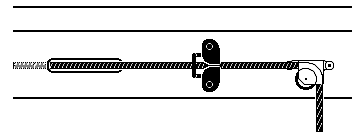
Fig. 5-12 Cleat on centreboard case collar
-
Cleats on the thwart beam If one has a thwart beam of the kind on the Robert Franz JETONs, the cleats can be mounted directly on it with pulling direction outboard. The trim lines are deflected outboard at the centreboard case.
-
Trim bench
This is a retrofit fitting screwed outboard onto the traveller track. The trim lines are deflected outboard with blocks mounted on the traveller support (Figs. 5-2, 5-3, 5-11.). In Chapter 6 you will find installation instructions for the trim bench. If the trim lines are to be belayed outboard, they must have two hauling tails. This is achieved with a doubler (Fig. 5-13). A doubler is always at the same time also a purchase and halves the force.
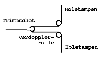
Fig. 5-13 Doubler
For jib cunningham, jib fairlead adjustment and topping lift there are yet other systems, which are described there.
Kicking Strap
The kicking strap is meant to prevent the boom from rising. In doing so it keeps the mainsail flat. This is important above all with the mainsheet eased. Part of this task can be taken over by the traveller. If one uses a wire strop bridle, the kicking strap must be laid out so that it does the whole work.
The kicking strap also controls the mast bend in the lower area and the twist of the mainsail, or the opening of the leech. The standard kicking strap is a three-part tackle that can be belayed on an integrated jam cleat. A four-part purchase is, from experience, undersized; 8-part is sufficient. In Fig. 5-14 two solutions with 8-part (a) and 16-part (b) purchase are described.
Fig. 5-14 Kicking strap, a. cascade, b. with highfield lever
The deflection aft is done in both designs on both sides at the mast foot. The trim lines are deflected outboard at the thwart beam or traveller and belayed there. If a single trim line is to be used, it is led aft on one side only and belayed in the middle at the traveller support.
Cunningham
The cunningham serves to stretch the mainsail luff. Thereby the mainsail becomes flatter and the belly is moved forward. The cunningham can in principle be run directly, i.e. without a purchase. Better, however, is a two-part purchase. The purchase can most simply be achieved by pulling the cunningham line directly through the cunningham cringle, deflecting it aft on both sides at the mast foot and belaying it outboard at the traveller or thwart beam. A purchase with a block is, however, smoother-running. This can also be the doubler block at the same time. Since the travel of the cunningham is not very great, it can simply be deflected aft. The doubler block then runs between the mast and the leading edge of the centreboard case (Fig. 5-15 b.). If the cunningham is to be belayed in the middle at the thwart beam or the traveller support, it can be given a purchase either with a block between the mast and the deflection aft (Fig. 5-15 a.) or with a block shortly before the belaying. Particularly elegant is a cunningham running inside the mast, led into the mast through a slot below the gooseneck fitting and then deflected aft with an entry sheave (Fig. 5-15 c.).
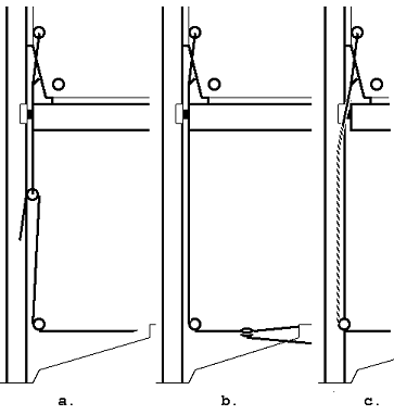
Fig. 5-15 Cunningham,
a. Simple belaying,
b. For belaying outboard, with doubler,
c. Internal cunningham.
Outhaul (Foot Stretcher)
The outhaul serves to trim the mainsail profile in the lower area. Modern mainsails are mostly profiled down to the lowest panel. Between the lowest panel and the foot there is an “ellipse.” This is a further panel of soft cloth. If the outhaul is eased, this panel lies horizontally between the boom and the first panel. If one hauls the outhaul tight, the lowest panel is pulled flat and the ellipse forms a fold along the boom. The outhaul is therefore an important trim instrument, since it must, e.g., be hauled tight on a windward course and eased on a reach. It should therefore in any case be operable from the cockpit, from outboard if possible.
For leading the outhaul, a deflection block at the boom end and one at the forward end are necessary. Depending on taste, the outhaul should have a purchase. One needs quite a lot of force to haul it tight. On the other hand, too great a purchase prevents it from easing in light wind. I think a four-part purchase is good. This is achieved by a cascade of two two-part purchases. The last stage should be the doubler (Fig. 5-16 b). A further two-part purchase can be fitted either in the boom (Fig. 5-16 a) or at the boom end (Fig. 5-16 b). If one uses both, one obtains an eight-part purchase. If one does not need a doubler, one should, to achieve a four-part purchase, use a two-part purchase both in the boom and at the boom end.
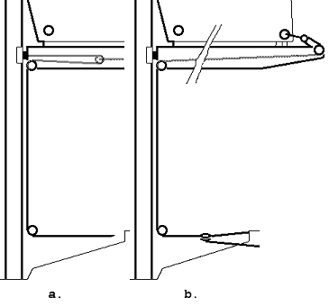
Fig. 5-16 Outhaul,
a. for belaying in the middle, with purchase in the boom,
b. with doubler for two-sided belaying, and purchase at the boom end
On the Ermat boom there is no device for leading the outhaul. Here a deflection block must be riveted onto the boom end at the rear. Very well suited is the spinnaker halyard sheave, which after all is left over when one has fitted an internal spinnaker halyard. At the front a normal entry sheave must be fitted. The Klepper boom already has a deflection block at the rear, so that one only needs the entry sheave at the front. Booms from Superspars and Proctor already have all the blocks.
Jib Cunningham
The jib cunningham serves to stretch the jib luff. It is often already present from the sailmaker in the form of a lashing. Some, however, want to use it for trim and must therefore lead it aft. For this a lying block is mounted on the forestay fitting, which deflects the jib cunningham (Kevlar or Dyneema) aft. The jib cunningham should have a two-part purchase. As belaying a jam cleat on the mast controller is sufficient. Another option is to use a doubler and to mount two jam cleats on the deck in the area of the wave breaker.