CONVERSIONS & DIY GUIDES
Contents
- Measuring the Mast
- Converting the Measurement Band MVS
- When You Need a New Mast…
- Mast Controller with Support onto the Side Deck
- Jib Fairlead on Track
- Free-flying Fairlead
- Leeward Sheet Belaying on the Original Track
- Mainsheet Table
- Installation Instructions Mainsheet Table A
- Installation Instructions Mainsheet Table B
- Internal Spinnaker Halyard / Internal Topping Lift
- Spinnaker Halyard Tackle
- Spreader Adjustment on the Cheap
- Centreboard Case Reinforcement
- Repair of a Split Centreboard Case or Rubbing Strake
- Centreboard Guidance
- Centreboard Control Line Lead Without a Cleat
- Improving the Centreboard
- Centreboard Repair
- Converting the Original Steering Gear
- Trim Bench
- Filling Holes / Gelcoat Damage
- Converting the JETON into a Cruising Boat
Measuring the Mast
Before any conversion work is carried out on the mast, one should measure it carefully. All measurement bands and also the target positions of all fittings should be marked.
Tools
Metal tape measure, at least 5 m.
Instructions
- With the mast standing, the measurement band M0 (highest position) is determined. This is done with a batten laid across the deck. This position is provisional, since in most cases it will turn out that the mast is somewhat too short, i.e. M0 lies a little below deck height.
- The mainsail is hoisted and fixed as high as possible. The upper edge of the head board defines the measurement band MII. If one now lays the boat on its side, one can also mark MII.
- Now the distance from M0 to MII is measured. If it is greater than 6960 mm, MII must be moved down. If it is smaller, M0 must be moved down.
- For the further measuring work it is best to lay the mast down or to leave the boat lying on its side. Now all dimensions are determined and marked.
Converting the Measurement Band MVS
This conversion is only necessary for older boats with an Ermat mast, on which the measurement band MVS is not at the correct height from the factory. This conversion is quite decisive for the windward behaviour of the boat. Since it is easy to carry out, one should indeed do it.
Material
- New jib halyard (about 200 mm longer)
- possibly new shrouds and new forestay.
- possibly a new bolt, because the old one is bent from the shroud load.
- Paint or a smudge-proof felt-tip pen.
Tools
- Drill
- Blind riveting pliers for aluminium rivets
- Brush, adhesive tape
Instructions
- Unscrew the mast fitting with shroud adjusters and jib halyard deflection sheave.
- Drill out the rivets of the spinnaker halyard sheave and remove the spinnaker halyard sheave.
- Determine the position of the new measurement band MVS (1700 mm below the measurement band MII at the masthead) and mark it with two strips of adhesive tape. In doing so one should take a copy of the class rules to hand and make sure that one makes no mistake. Then paint the space between the strips of adhesive tape in a contrasting colour and remove the tape strips later (Fig. 6-1).
- About 25 mm below the measurement band, holes for the mast fitting are now drilled in the mast (6 mm). This dimension has proved itself on the new masts.
- Mark the new position for the spinnaker halyard sheave 170 mm above the measurement band MVS and drill holes. Alternatively an internal spinnaker halyard can be fitted (Chapter 6, Internal Spinnaker Halyard).
- Screw the mast fitting back on.
- If applicable, rivet the spinnaker halyard sheave back on.
- Trim: Usually the shrouds, when hung in the last hole of the shroud adjuster plate, are just long enough. The mast rake is then just so strong that when the jib halyard is set, the clew hovers about 1–2 cm above the standard jib track, as it should be. If one wants to fit new jib sheet fairleads, still more mast rake is possible and possibly advantageous.
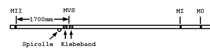
Fig. 6-1 Converting the measurement band MVS
When You Need a New Mast…
Very often I receive enquiries: “How and where do I get a new mast for the JETON—and, above all, quickly?”
Makes
There is a choice between three different makes:
- The Klepper mast (untapered only)
- Holt-Allan
- Superspars M2
- Proctor Epsilon
In principle there is with Superspars and Proctor also the choice between untapered and tapered. The advantages of a tapered mast are, however, so striking that the comparatively small extra cost should play no role. The advantages of the Proctor and Superspars masts over the Klepper mast are, besides the taper, above all the higher quality of the material and the fittings. The choice of make is first of all a question of price. The Klepper mast is of course considerably cheaper. But one should compare the correct prices. One should check whether halyards, standing rigging and trapeze wires are included in the price. If one is looking for a used mast, an advertisement in the ASJETON newsletter or yearbook helps.
Attention!
- If one replaces the existing mast with a new one of a different section, one usually needs new sails too, since the luff curve should be matched to the mast bend. Above all the taper of the mast must be taken into account in the mainsail cut.
- None of the mast makes is offered with a diamond. On the other hand, without a diamond a mast controller is absolutely required. Fitting an existing diamond to the new mast is emphatically advised against. One needs a mast controller if applicable.
- If one converts from a Klepper or Ermat mast to Holt-Allan, Superspars or Proctor, the old standing rigging, halyards and trapeze wires can no longer be used.
- The Ermat or Klepper boom does not fit the Holt-Allan, Superspars or Proctor gooseneck. One either decides to buy a new boom as well or must modify the end fitting of the existing boom. One must file out a square hole of 14 mm.
Mast Controller with Support onto the Side Deck
By Erich Beer
Material
- V2A stainless tube, 20 mm Ø, wall thickness 1 mm, length about 1 m
Material cost: about 30 DM
Tools
- Welding equipment
- Metal saw
- File
- Measuring tools
Instructions
- Mark the boat’s axis with a taut string.
- Bend the mast controller tubes (MCR), at equal distance to the boat’s axis, in or out so that the clear dimension is about mast width + 2×5 mm.
- Take the approximate dimension between the MCR and bow + an allowance of 10 mm.
- Fit V2A tube of 20 mm outer diameter, wall thickness 1 mm, exactly to the MCR.
- Fit a pressure-distribution plate of V2A, 3 mm thick, to the hull, with 4 drillings of about 4.5 mm Ø for 4 mm rivets.
- Cut the V2A tube to length, taking into account the pretension of the MCR of 1×5 mm each described under 2.), the thickness of the pressure-distribution plate and the angle of inclination.
- Push the V2A tube under pretension between the MCR and the pressure-distribution plate. (The MCR move closer together; observe mast width + 1 mm.)
- Tack-weld the V2A tube to the pressure-distribution plate (V2A). For this an experienced welder is required. Attention! When tacking, observe the heat flow into the hull shell. After about 10–15 seconds of cooling time, take out the V2A tube with the pressure-distribution plate and weld it completely.
- After riveting to the hull shell, join the V2A tube and MCR together with a 4 mm rivet.
Jib Fairlead on Track
Material
- Battens (mahogany), 20×10 mm²
- Sail batten 20×3 mm²
- Bracket fitting
- Angle track or arm for
- Slide
- Track, end pieces, slide
- Lying deflection blocks
- Upright deflection blocks
- Spring
- Screws, nuts, washers (M5)
Tools
- Drill
- Jigsaw
- Screwdriver
Preparatory Work
- Prefabricate the stiffeners. It is recommended to glue wooden strips (20×10 mm), which are still to be faced with sail batten, from the inside against the tank wall at the places where the fittings are to be mounted (sandwich construction). Certainly stiffeners of other materials can also be used. Aluminium sections were also used, but one should bear in mind that strength and elasticity should be matched to the GRP. The fittings are then screwed through the stiffeners with screws and self-locking nuts.
For the fairlead with the track and the bracket, four battens are needed per side, in total:
2 wooden battens 350 mm
2 wooden battens 100 mm
4 wooden battens 300 mm
2 pieces of sail batten 300 mm
2 pieces of sail batten 50 mm
4 pieces of sail batten 200 mm
The sail battens are glued onto the wooden battens per Fig. 6-2 a. This is done with adhesive resin. UHU-Plus (fast-setting) is also suitable. This is indeed relatively expensive but easy to obtain. Professionals use adhesive resin, such as is also used to bond the JETON shells. Fibre filler, such as is available for car repairs, will certainly also do.
- Screw together the bracket with block and cleat. If the Harken cleat is used, raise the block with the help of spacers! The becket is screwed to the aft-facing screw of the cleat. Note: it may be that one or another becket must be bent somewhat to make it fit (Fig. 6-2 a.).
Note: If an angle section is used for the fairlead track, the fairlead track and the end pieces should be screwed on only after installation in the boat.
Fixing the Position
Before one begins to drill holes, all parts should first be stuck into the boat with double-sided adhesive tape per Fig. 6-2. One should pull the jib sheet through once and check whether everything works as it should. The position of the bracket with the Cleat is in principle arbitrary. One should ensure that the angle of the block suits the direction of the sheet pull and that the sheet does not rub anywhere. The bracket should also not be fitted too high, so that one does not knock into it. The shape of the bracket was chosen specially so that with correct installation the cleat is inclined aft. This makes it easier to knock the belayed sheet out. The dimensions given in the drawing have proved themselves on my boats.
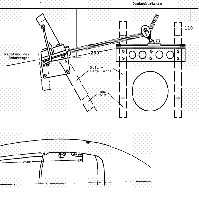
Fig. 6-2 Mounting the jib fairlead
a. Bracket, track, reinforcements
b. Position
Installation Instructions
- Inspection hatch: With the help of the lid, mark a circle. Drill a hole and saw out the circle with a jigsaw, or drill holes every 10 mm along the circle (5 mm) and break out the webs with a saw blade. Rasp the hole round with a rasp until the hatch fits in.
- Note: fit hatches after everything else has been fitted! It also works through the fitted hatches, but is easier beforehand.
- Crumble out and remove the styrofoam.
- Drill holes for all fittings!
- Drill holes in the battens, Fig. 6-2 a.
- Glue in the battens with adhesive resin or UHU-Plus, first roughening the GRP with coarse sandpaper. Ensure that the drilled holes in the battens and in the GRP line up. UHU-Plus fast-setting is dry in 10 minutes. Fix with clamps as far as possible.
- Screw down all fittings, seal with silicone paste.
- Drill holes for fastening the inspection hatches. Glue in the inspection hatches with silicone paste and fasten with self-tapping screws or, better, with pop rivets.
- If an angle section is used, screw the track with slide onto the already mounted angle section.
- Put new styrofoam pieces into the side tanks (e.g. balls).
- Pull the sheet through and sail, sail and sail.
Free-flying Fairlead
Reinforcements for the fastening eyes of the bridle are not necessary, since on one side the already existing reinforcement at the centreboard case is used. The outboard eye sits at a place that is quite strong in terms of laminate. Furthermore the force attaches tangentially.
Material
- Bracket with deflection block, cleat and becket, complete.
- 5 fender eyes
- 4 blocks
- Screws, nuts, washers
Tools
- Drill, drill bits
- Screwdriver
- Silicone
Instructions
- Installation of the bracket with deflection block and cleat as for the fairlead on track.
- Just above the cockpit floor a fender eye with deflection block is fitted to the side tank (B in Fig. 5-3).
- A fender eye is screwed over the mounting plate of the toe straps at the transom (A in Fig. 5-3).
- One fender eye each with deflection block is fitted either directly at the traveller outboard or at the side tank near the traveller.
Leeward Sheet Belaying on the Original Track
By Erich Beer
This leeward sheet belaying has the advantage over other systems that no further holes need to be drilled in the hull. Through the movably mounted cleat plate it is possible for the crew to operate the jib easily and simply from any position. Although the original track is used, the jib fairleads can be moved further inboard. If one drills several holes in the stainless plate, one has the possibility of finding the correct trim for one’s boat or one’s sails. A good guideline for the distance between the centre of the eye and the centre of the jib track is 50 mm. Whoever wants to run the jib further inboard still has enough room.
Material
- 2 stainless steel plates about 110–130 × 45 × 3 mm, depending on jib attachment angle
- 2 aluminium or stainless steel plates 90 × 90 × 3 mm
- 2 swivelling metal eyes, which are probably only available in combination with the slide.
The two existing Cleats can be used but need a becket. Better, however, would be two smooth-running Servo cleats.
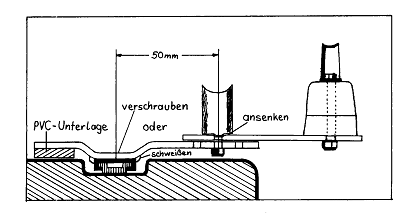
Fig. 6-3 Fairlead system on the original jib track
Instructions
First the metal eyes are separated from the slide. Please take care when clamping the slides that they are not bent, because otherwise they no longer fit on the track. Now the stainless plate is bent slightly, so that it can be moved on deck without obstruction. Then it is welded or screwed to the slide. Attention: make a right and left side. A PVC underlay is fastened to the stainless plate. This distributes the resulting pressure better over the deck and prevents unsightly scratches. The hole for the eye must be countersunk somewhat from above, so that it sits better on the aluminium plate. Now the Cleat is mounted on the correspondingly cut aluminium plate. Then one joins the eye and the two plate parts by means of a countersunk screw and a self-locking nut. Now the finished leeward sheet belaying can be pushed into the jib sheet track.
Mainsheet Table
As described in Chapter 5, there are two versions of a mainsheet table for mounting a Mubir block. The fitting parts are unfortunately now out of stock. Dimensioned sketches for making the parts are available from the editor. The installation of both fittings is described here.
Material
- Stainless fitting mainsheet table A or B
- Mubir block
- Screws, washer, nut
Tools
- Drill, drill bits 4 mm, 5.5 mm Ø
- Screwdriver
- Spanner 8 mm
- Thread cutter M5
Installation Instructions Mainsheet Table A
- Unscrew the old eye for the mainsheet block. Fill in the topmost of the three holes (section Filling Holes).
- Place the stainless fitting on the centreboard case so that the upper edge is flush with the upper edge of the centreboard case.
- Mark point A (Fig. 6-4) with a felt-tip pen.
- Measure the distance from the mark to the threaded holes on the centreboard case (A-B, A-C).
- Hold the stainless fitting up again and mark point D for the drilling in the centreboard case.
- Drilling in the centreboard case 5–5.5 mm Ø.
- Mark and drill holes in the stainless fitting (5.5 mm Ø).
- Screw the Mubir block to the stainless fitting with countersunk screws and nuts.
- Screw the stainless fitting to the centreboard case: two into the already existing threaded holes; into the newly drilled hole insert the screw from the front (with a washer underneath) and put the nut on from behind. Seal all holes with silicone.
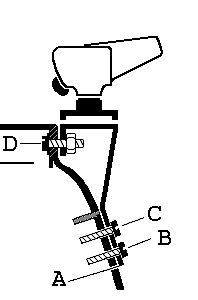
Fig. 6-4 Installation of mainsheet table
Installation Instructions Mainsheet Table B
- For mounting the mainsheet table, the laminated-in plates are used to which the original cleats for the centreboard uphaul and downhaul are screwed. The cleats must be unscrewed if necessary. The rear threaded holes are filled (section Filling Holes); the front threaded holes are used to mount the stainless fitting.
- Hold the stainless fitting up so that the front hole lies over the front hole of the cleat. Mark the rear hole.
- Drill the marked holes (4 mm Ø) and cut threads into the laminated-in plates (M5).
- Screw the Mubir block to the stainless fitting with countersunk screws and nuts.
- Screw the stainless fitting to the centreboard case with four screws.
Internal Spinnaker Halyard / Internal Topping Lift
Material
- Deflection block on the mast (HS lying block + YF 000) (if not already present)
- Entry sheave
- 15 m spinnaker halyard 4 mm Ø braided and pre-stretched, or 3 mm Dyneema.
Instructions
- The old spinnaker halyard sheave is removed by drilling out the rivets.
- To fit the entry sheave a square slot must be made in the mast. The slot is marked out so that the upper edge of the sheave, when fitted, lies 170 mm above the band MVS. Take care with the position of the holes for the entry sheave! If one has no milling cutter to hand, which is probably true for most, one drills a row of holes, breaks out the webs and files the hole square.
- Now the tabs of the sheave are bent so that they adapt to the curvature of the mast. Holes are drilled and the sheave screwed in with self-tapping screws.
- Above the mast foot a square hole is filed. The lying block is fitted internally with two screws or one screw and pop rivet (Fig. 6-5). I recommend replacing the sheave of the lying block with a ball-bearing YF 000; then an M4 screw must be used. Alternatively the spinnaker halyard can be led out of the mast through a lateral slot. A lying block fitted outside below the slot serves to deflect the halyard forward.
- The spinnaker halyard can best be pulled through with the help of a shroud or a halyard wire.
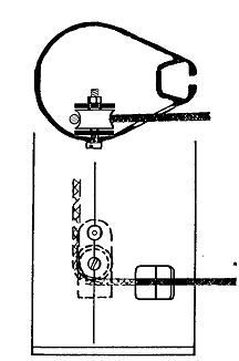
Fig. 6-5 Spinnaker halyard exit at the mast foot
Spinnaker Halyard Tackle
Material
- Deflection block on the mast (HS lying block + YF 000) (if not already present), or other lying ball-bearing block
- Double block
- Double block with becket
- Fender eye
- Cleat with becket (SERVO 22 + front becket)
Instructions
- Fit the fender eye (Fig. 4-8): Measure the position: 100 mm from the boat’s centre, centre of the eye 80 mm above the floor. The holes can simply be drilled through (Ø 5 mm). The eye is bolted with screws (M5), large washers (commercially available 15 mm Ø) and nuts. Further stiffeners are not necessary, since the transverse bulkhead is laminated strongly enough.
- Screw the Cleat to the traveller support with two screws. Drill holes beforehand (5 mm Ø).
- If there is no deflection block on the mast, one must be fitted. I recommend leading the spinnaker halyard inside the mast. For an external spinnaker halyard the lying block must be fitted to the mast with two self-tapping screws or pop rivets.
Spreader Adjustment on the Cheap
Commercially available spreader adjusters are expensive. There is a simple, cheap method of adjusting the spreaders: a thread is drilled at the mast-facing end of the spreader. A screw set into the thread then serves as a stop for the spreader in the spreader fitting. By screwing the screw in and out, the spreader angle is adjusted.
Material
- 2 screws M5×20
Tools
- Drill, drill bit 4 mm Ø, countersink
- M5 tap
- File
- Hammer and centre punch
- Metal saw
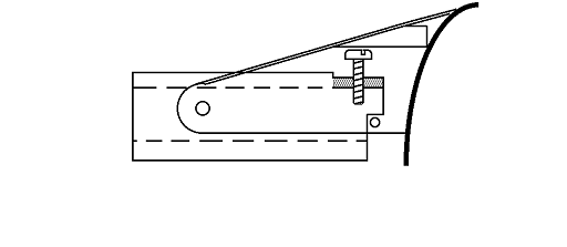
Fig. 6-6 Simple spreader adjuster
- Remove the spreader.
- At the mast-facing end, file a flat of about 10×3 mm on the round front side of the spreader section.
- About 5 mm from the spreader end (in the middle of the filed flat), centre-punch and drill a hole of 4 mm Ø.
- Countersink the hole and cut a thread (M5).
- The spreader is generally fastened in the spreader fitting with two screws or bolts with a circlip. The screw (or bolt) further from the mast is still needed as the pivot point of the adjustable spreader. The second screw (or bolt) is only needed as a stop, to prevent the spreader from folding forward. With saw and file, a recess is to be made in the spreader, so that the spreader can be adjusted within the desired range, but a stop is created so that the spreader cannot fold forward.
- Now the spreader can be adjusted with the help of the two screws: if the screw is screwed in, the spreader angle becomes more acute; by screwing it out it becomes more obtuse.
Centreboard Case Reinforcement
From an article by Hans Spannheimer.
There is no question, the centreboard case is a critical point on all trapeze dinghies. One need only look once at the effort involved in supporting the centreboard case in a 505, 470 or Korsar to realize quickly that this is no easy problem. With almost every new model the centreboard case changes on the boats mentioned. An ideal solution—light, durable and stable—does not yet seem to have been found. On the JETON the centreboard case was a weak point from the start. The deep and relatively broad JETON centreboard transfers enormous forces to the upper edge of the centreboard case. These forces cause essentially two deformations:
- The centreboard case bends as a whole to the side.
- The upper part of the loaded side wall of the centreboard case bends outward under load.
To prevent the first deformation with suitable reinforcements is not easy. But much is already achieved if one eliminates the problem mentioned under point 2.
The migration of the centreboard out of the centre can, according to measurements on my own boat, be reduced by 50–60% thereby. If one does nothing against the bending of the side walls of the centreboard case in the upper area, then the bond of the outer shell with the inner shell bursts open at this point. Some JETON sailors have re-glued these burst areas. Without reinforcement of the upper edge of the centreboard case this is a useless undertaking.
There are various ways of reinforcing the upper edge of the centreboard case. Some JETON owners have built a frame of aluminium square tube around the centreboard case. This frame (square tube 40×20×2 mm) weighs at least 1.5 kg. In the area of the holding rods for the centreboard, difficulties arise because of the bulges. On the always cold-feeling aluminium the crew does not sit very comfortably. For this and a few other reasons (risk of injury on the projecting sections, appearance), I chose a different solution, which I would like to describe briefly.
Instructions
The upper edge of the centreboard case, at a thickness of about 10 mm, is much too thin. As Fig. 6-7 shows, the upper edge is stiffened by a sandwich construction. First, one glues with epoxy adhesive two wooden strips, about 1 m long, 2.0–2.5 cm wide and 3.0 cm high, flush against the centreboard case. The wood needs no particular strength. It should be as light as possible (e.g. spruce, red cedar or similar). Onto each strip a sail batten of cross-section 30×2 mm is likewise glued with epoxy resin. All glue surfaces must first be roughened with sandpaper. To press on a strip or a sail batten one needs a few clamps. As adhesive one should use only viscous resin; best thickened beforehand with microfiller! With thin adhesives one usually has more resin on the boat floor than in the glue joint. After curing, everything is sanded smooth, filled, sanded again and then varnished.
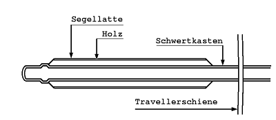
Fig. 6-7 Centreboard case reinforcement
Repair of a Split Centreboard Case or Rubbing Strake
The Damage
As described in the previous section, the bond of the lower and upper shell sometimes comes loose at the upper edge of the centreboard case through the working of the centreboard. Similar damage also occurs at the bond at the rubbing strake, above all in collisions.
The glue joint at the centreboard case is relatively thick on newer boats, 10–15 mm; on older boats only about 8–10 mm. Since the laminate is at most only 3 mm thick, a considerable part is adhesive resin. In the adhesive resin layer, fine cracks usually form first, above all at the ends of the centreboard case. The fine cracks can in the worst case also tear open completely.
The adhesive resin layer at the rubbing strake varies from 5 to 15 mm.
Instructions
The cracks must be opened as wide as possible. This is best done by drilling out with a drill bit of about 3 mm. Then the crack is sawn open with a jigsaw. Caution: drill or saw away only adhesive resin. But one should remove all loose or cracked parts of the adhesive resin if possible.
For the repair at the rubbing strake the boat must be turned upside down. The loose adhesive resin parts should be removed with a chisel.
Surfaces that did not arise from sawing or drilling, e.g. fracture edges, must be roughened before gluing. Now fill the opened gap with thickened adhesive resin.
Attention: Do not repair both sides of the centreboard case at once. The centreboard case could become too unstable, and the bond becomes skewed.
Fine-fill the filled areas if necessary, sand and coat with topcoat.
Centreboard Guidance
How the lateral guidance of the centreboard should be laid out was described in Chapter 5. This do-it-yourself suggestion shows how one can achieve this with a few pieces of sail batten and some skill. If one already has a centreboard case collar from Robert Franz, one only needs the vertical guide strips.
The fitting and installation of the horizontal guide strip can also be done with the centreboard fitted. Then one can check with the centreboard right away whether everything fits. For the vertical guide strips the centreboard must be removed.
When working the sail batten it is advisable to wear a fine-dust mask, since the sail batten is of glass-fibre material.
Material
- Sail batten, thickness 3 mm, width 30 mm, length 1.20 m
- Adhesive resin
Tools
- File,
- Fine saw,
- Sandpaper (grit 40, 100),
- Vernier calliper,
- Batten of the thickness of the centreboard as a gauge,
- Fine-dust mask.
Instructions
- From the sail batten, four pieces are cut—two each … long and two pieces … long.
- The horizontal guide strips must be fitted. At the place where the vertical guide strip already is in the centreboard case, the horizontal guide strip must be notched. For this the sail batten is cut into somewhat with the fine saw and the material lying between the cuts is filed out. Since the centreboard case becomes somewhat narrower towards the front from the vertical guide, the batten may have to be tapered somewhat. Check with the gauge or the centreboard itself.
- Glue in the horizontal guide strip. The adhesive resin should be viscous. If the thickness of the batten is not quite sufficient, the gap can be made up with adhesive resin. Check with the gauge or the centreboard itself.
- The vertical guide strips must be tapered wedge-shaped. At the top they may only be about 1.5 mm thick. Since the centreboard case becomes wider towards the bottom, the full thickness of the batten is needed at the bottom. If necessary, even two battens must be glued on top of each other. The sail batten is first worked roughly with 40-grit sandpaper. Smooth with 100-grit sandpaper or the file. Check with the gauge.
- Glue in the vertical guide strip. Check with the gauge.
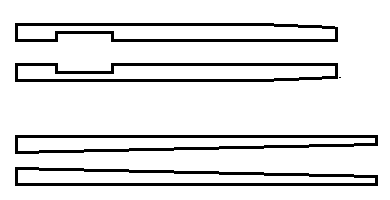
Fig. 6-8 Guide battens for the centreboard case
Centreboard Control Line Lead Without a Cleat
In Chapter 5 the continuous centreboard control line lead was described (Fig. 5-9). Here the installation in the original JETON and in a JETON with a centreboard case collar is described.
Material
- Centreboard control line: 6.50 m, 6 mm Ø,
- Shockcord: about 2.00 m long, 5 mm Ø,
- End,
- Screws
- For original JETON: Centreboard case collar:
- 2 lying blocks, 4 lying blocks,
- 2 upright blocks, 1 upright block,
- 2 fender eyes.
Instructions
Original JETON:
- Two deflection blocks are fitted at the centreboard head. Either lying blocks are screwed on (as in Fig. 5-9, (B)) or blocks are lashed on.
- An eye is mounted amidships at the transom. This is easy because of the existing inspection hatch. Put a plate or large washers under the nuts! Do not forget to seal with silicone! A block (C) is fastened to it with a strong shockcord strop (take 6-part).
- On newer JETONs there is a fender eye with block on the keelson behind the mast (A), through which the centreboard uphaul is led. Older JETONs instead have a plastic eye. This is removed and replaced by a fender eye with block.
- As shown in Fig. 5-9a, the centreboard control line is fastened at the eye on the keelson (A), led over a block at the centreboard head (B) back to the block on the keelson (A), deflected aft there. It is led through the block fastened at the transom (C), from there back to the centreboard head, through the second block (B) and is finally tied to the traveller support.
With centreboard case collar
- Two deflection blocks are fitted at the centreboard head. Either lying blocks are screwed on (as in Fig. 5-9(B)), or blocks are lashed on.
- Two lying blocks are mounted on the centreboard case collar (D).
- The centreboard case collar gets a hole (about 12 mm Ø) (E).
- On newer JETONs there is a fender eye with block on the keelson behind the mast (A), through which the centreboard uphaul is led. Older JETONs instead have a plastic eye. This is removed and replaced by a fender eye with block. The block is fitted with a Kevlar or wire strop about 10 cm long.
- As shown in Fig. 5-9 b, the centreboard control line is fastened at the eye on the keelson (A), led over a block at the centreboard head (B) back to the block on the keelson (A), deflected aft there. It is pulled through the lying blocks (D), from there back to the centreboard head, through the second block (B) and led through the hole under the centreboard case collar (E). There a shockcord strop is knotted, which can be fastened, e.g., with an eye or screw (F).
The centreboard can now be operated at the eye by shifting the line into any position, by both the helmsman and the crew. The shockcord strop is necessary to compensate for the change of length of the line in the various centreboard positions. It should still be slightly tensioned with the centreboard lowered. It has proved advantageous to tension, parallel to the shockcord strop, an end that is just taut when the centreboard is raised. Then the centreboard control line can also be hauled over the block at the stern. With the centreboard case collar this is automatically the case, since the knot cannot slip through the hole.
Improving the Centreboard
By Jupp Zavelberg
On closer inspection the original centreboard can only be regarded as the blank of a good centreboard. Whoever wants to achieve something with little work should remove the edges with a coarse file or rasp and produce a smooth surface again with sandpaper in the direction of flow. If, after varnishing, fine filler is used, an acceptable surface is quickly obtained. Whoever varnishes clear (natural) has more work. One should obtain a collection of profiles or use one of the profiles given in Table 8-1 (see APPENDIX, section Profiles).
Editor’s note: A fully profiled centreboard is very prone to breakage because of its shape. This improvement should therefore not be carried out without simultaneous reinforcement.
Centreboard Repair
This repair guide comes from an article by Hans Spannheimer.
As described in Chapter 5, JETON centreboards have a weak point owing to their construction. They break easily along the line D-D in Fig. 5-7.
Introduction
There is a relatively simple method of reinforcing the centreboard so that it, with some certainty, no longer breaks and moreover becomes extremely stiff. The method consists of laminating carbon fibres onto the centreboard (hatched area in Fig. 5-7). Now do not stop reading because you tell yourself, laminating I have never done, I can’t do that. The thing is much simpler than you imagine.
Material
- about 2 m of carbon-fibre tape about 7.5 cm wide,
- 100 g to 150 g of epoxy resin (on no account polyester resin),
- two completely smooth and flat wooden boards about 25 × 50 cm, best of 20 mm thick chipboard,
- 0.5 m² of polyethylene film 0.5 mm thick.
Tools
- Flat brush 3–4 cm wide,
- Sandpaper of grit 30 or 40,
- Gloves
The carbon-fibre tape (unidirectional layup) and the epoxy resin you can buy in model-making shops.
Instructions
Where the carbon fibres are to be glued on, you sand the wood on both sides of the centreboard about 1 mm deep with the coarse sandpaper. An orbital sander makes this work much easier. The carbon-fibre tape is cut into strips of about 35 cm length. In a small glass vessel the epoxy resin is mixed with the hardener and thoroughly stirred. You apply the resin with the brush to the sanded area of the centreboard. Onto this you lay the first carbon-fibre strip. This strip is now coated with epoxy resin, holding it at one end each time. In this way you continue and glue at least 3 strips on top of each other. The laminate is covered with a piece of polyethylene film and a board. Polyethylene film does not bond with epoxy resin. You press the board firmly onto the centreboard with a few clamps. Thereby, after curing (about 4 hrs.), one achieves a flat surface. With the second side of the centreboard you proceed the same way.
Should some unevennesses (depressions) remain, one can fill these with epoxy-resin filler. Epoxy-resin filler one can either buy in the boating supply trade or make oneself. For this one mixes microballoons (available in model-making or hobby shops) into the epoxy resin mixed with the hardener. Depending on the amount added, one obtains a viscous to doughy consistency. This thickened epoxy resin is also outstandingly suitable as an adhesive for polyester, wood and metal. Even a broken centreboard can be glued back together with it and reinforced as described above.
Other Materials
Strip-laminated centreboards:
strip-laminated centreboards break along the line D-D. One should therefore reinforce them in the manner described. Here too a repair after a longitudinal break is possible. The prerequisite for a repair is of course always that the fracture pieces can be reassembled perfectly. If the centreboard splinters very badly when breaking, this can cause considerable difficulties.
Plywood centreboards:
Plywood centreboards do not break along the line D-D in Fig. 5-7 either. When they break, the eccentric tenon breaks off at about C-C.
A very effective reinforcement is achieved by laminating on carbon-fibre strips about 50–60 cm long, similar to what is shown in Fig. 5-7, but the angle between the strips and the trailing edge of the centreboard should be clearly smaller (about 25°, roughly in the direction B towards the base point Fa).
Self-building of Plywood Centreboards
The disadvantage of plywood centreboards is the low bending stiffness. They offer the advantage that they warp even less than the already quite dimensionally stable strip-laminated centreboards. Because of the lower bending stiffness, plywood centreboards should be at least 25 mm thick. There is also plywood reinforced in the longitudinal direction. This consists of many layers with grain in the longitudinal direction and few layers with grain perpendicular to it. It goes without saying that one must reckon here with delivery times and special prices.
Whoever wants to build a really good centreboard themselves is recommended, as material, normal plywood of Sipo mahogany of strength group F1, 25 to 28 mm thick, glued at least 11-ply, bonding per AW100 in accordance with DIN 68705 (all-weatherproof, waterproof, boil-proof). The centreboard should then be reinforced with carbon fibres and suitably profiled.
Converting the Original Steering Gear
The problem that the original rudder tiller is (sometimes much) too short can be eliminated by the following radical cure.
Material
- Aluminium square section, 40×20×2, length about 1.20 m,
- Pop rivets,
- Screws M5×20.
Tools
- Cutting disc, or metal saw,
- Drill,
- Drill bits 4 mm, 5 mm, 10 mm, countersink,
- Thread cutter M5,
- File,
- Blind riveting pliers,
- Screwdriver.
Instructions
- Cut off the upper part of the rudder head, into which the old tiller tube is inserted, with the cutting disc or metal saw.
- File the surface flat and fit it to the aluminium section tube.
- Drill 4 holes for screws through the section tube. First holes of 4 mm Ø thread (M5) are drilled, so that the positions can be transferred exactly onto the rudder head. If the holes fit badly, they must be drilled out later, and one has play.
- With the positioning, care must be taken that later, when screwing down, the screw heads must have room inside the section tube.
- Lay the section tube onto the rudder head and drill holes to fit (4 mm Ø) into the rudder head.
- Countersink and cut threads in the holes in the rudder head.
- The holes on one side of the section tube are drilled out to 5 mm (for the screws), on the other side to 10 mm (for the screwdriver).
- Saw the tiller to the correct length.
- At the end, drill holes for fitting the tiller extension and holes for cleats.
- Screw the tiller onto the rudder head.
- Fit the extension and cleats.
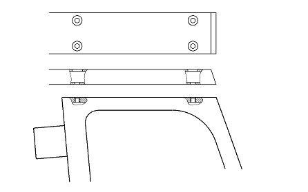
Fig. 6-9 Rudder tiller Klepper rudder head
Trim Bench
Material
- Trim bench fitting
- 6 Cleats Servo 11
- 3 double blocks
- 3 stainless tabs for mounting the deflection blocks
- Screws, nuts, washers (M5)
Tools
- Drill, drill bits 4 mm, 5 mm Ø
- Screwdriver
- Thread cutter M5
Instructions
- Drill two holes each into the traveller track on both sides, distance from the stopper screw about 100 mm and 200 mm respectively (A in Fig. 6-10a). If a thread cutter is to hand, these should be threaded holes. If nuts are to be used, the holes must be countersunk from above.
- Position the trim bench fitting so that the rounded corner rests on the side tank (B), and mark and drill holes in the trim bench fitting corresponding to the holes drilled in the traveller track.
- Screw down the fitting.
- Bend the stainless tabs for the deflection blocks to shape (Fig. 6-10b). Clamp part C into the vice up to the dashed line and twist the end with pliers. Additionally bend parts D, E so that the ends have the correct direction for fitting the blocks.
- Screw the stainless tabs to the traveller support. In doing so, the holes of the old Cleats, which are now no longer needed, should be used. Whoever wants to place the deflection blocks differently can of course do so. The tabs can also, e.g., be fitted lower on the traveller support.
- Fit the deflection blocks in the tabs (Fig. 6-10c).
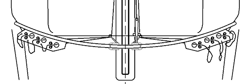
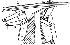
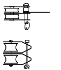
Fig. 6-10 Installation of the trim bench fitting,
a. Bolting to the traveller,
b. Fastening tabs (example),
c. Fastening of the blocks
Filling Holes / Gelcoat Damage
When one unscrews fittings and replaces them with others, holes often remain in the boat, which must of course be closed. As a provisional measure one can of course stick a piece of tape over them. In the long term, however, one should seal the holes. The problem with this is that the holes were sealed with silicone when screwing down. Filler does not hold on that.
Instructions
- Drill out the holes to remove the silicone.
- Fill the holes with fibre filler. For small holes, polyester fine filler also suffices, better epoxy fine filler. So that the repair is also visually perfect, one can then also work with gelcoat filler. When filling the holes one should then leave about 1 mm of space for gelcoat. The following procedure is suitable not only as a finish for filled holes but also for repairing cracks. Gelcoat filler one can buy ready-made or make oneself from gelcoat and Aerosil.
- Cover the prepared holes with two layers of packing tape.
- With a carpet knife, cut the packing tape along the edge of the hole, so that the surface to be repaired is exposed but the surrounding gelcoat surface stays protected.
- Fill the taped-off holes with gelcoat filler. Often more than one pass is necessary, because thick layers of gelcoat cannot be filled. If the repair spot is on a rough (textured) surface, one can already try, while filling, to give the filled surface some texture. On smooth surfaces the filler is drawn as smooth as possible.
- When the gelcoat is firm, on a textured surface the tape is pulled off and the surface reworked with a chisel, so that the repaired surface becomes as similar as possible to its surroundings.
- On a smooth surface, the filled area is first carefully sanded down wet to the level of the tape. For this too one should not use too coarse a sandpaper (at most 280 grit).
- Then the first layer of tape is pulled off. With 400-grit sandpaper one now carefully continues sanding, until the level of the tape is reached again. One should use a sanding block. Keep the sanding block straight, so that one does not sand through the tape. All scratches must afterwards be sanded out again.
- The second tape is also removed. Now one continues sanding with 600-grit sandpaper, until the surface is smooth. In doing so, the surroundings are also lightly sanded.
- The final sanding is done with 1000- or 1200-grit sandpaper.
- With polishing compound one can make the thus-prepared surface high-gloss, so that one no longer sees the repairs at all, at least if the gelcoat was the right colour.
Buttons
At some places in Chapter 5, “buttons” are mentioned. This is a simple way of turning a screw already on the boat into a fastening point for an end or wire strop.
For this one needs only 3–5 washers of normal size and one washer of larger diameter. The large washer is placed directly under the screw head, the small ones come below it. Then the screw is screwed back in, so that a button is created, over which an eye can be laid. E.g. the screws with which the traveller support is screwed down are suitable for this.
Converting the JETON into a Cruising Boat
Jutta and Wulf Rüthrich reported in the 1984/85 yearbook about a cruise with the JETON. For this they fitted a large hatch into the transverse bulkhead, in order to be able to stow luggage. Here is the construction guide from Jutta Rüthrich:
I can well imagine my husband’s heart pounding as he started up the jigsaw. Especially as he had always put this job off, until the last moment. I had already driven a week earlier with our son to grandma’s, to get him used to it for his first holidays alone, and so I could not dispel my husband’s misgivings about whether the boat would take it and whether the whole thing would afterwards also be watertight. But then it was done, he could at last crawl into the interior. From there he then reinforced it, below the hole across the entire width of the boat, with glass-fibre mat and laminate, and screwed 4 hooks under the deck. There we wanted to stretch a net for an emergency set of clothes, in case we “fall in the drink” and the “hole” is not watertight. Onto the cut edge on the boat the section was then clamped, which we, after a long search, were able to buy from the boatbuilder of our first boat (Achat). Then the flap was sawn from 6 mm plywood, 3 cm larger all around than the piece cut out of the boat, and varnished. The size, by the way, resulted from the height of the mast controller minus travel and the width of the boat, so that the flap can be pulled away to the side. At the top a lock with a turn-latch, likewise from the Achat, was fitted, and at the bottom a tab of aluminium, which pulls the flap firmly against the rubber seal. In the meantime the trial by fire has been passed, the boat is watertight and has, besides the holiday cruise, already survived 2 regattas with strong winds, e.g. Zülpich, without the mast controller collapsing.
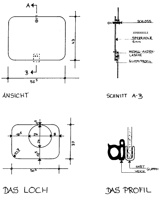
Fig. 6-11 Large hatch in the transverse bulkhead